

Home / Products / Piezometers / Drive-in piezometers
Reference products codes: PK45I, P235I
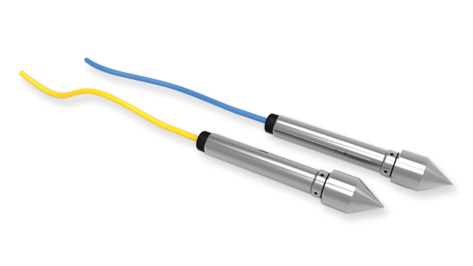
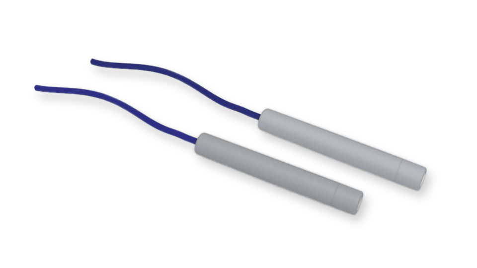
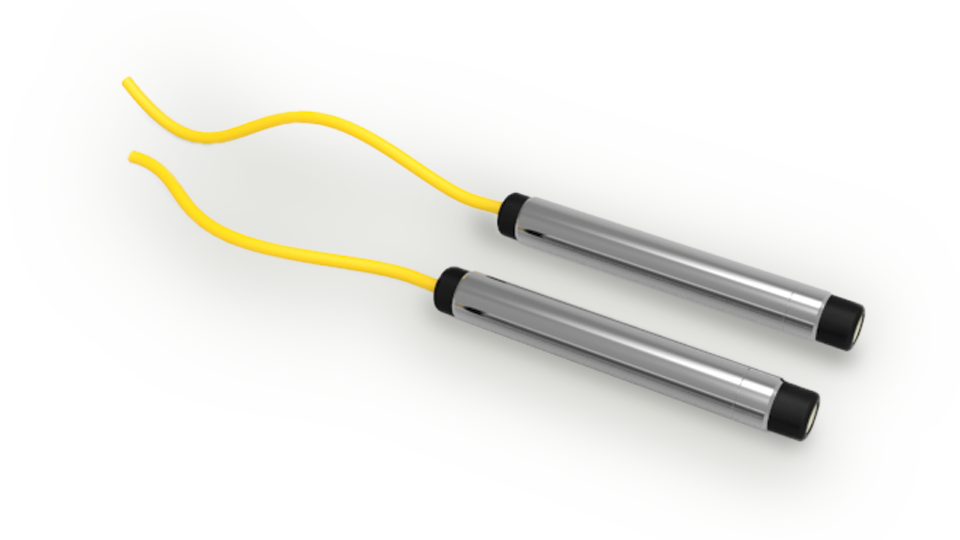
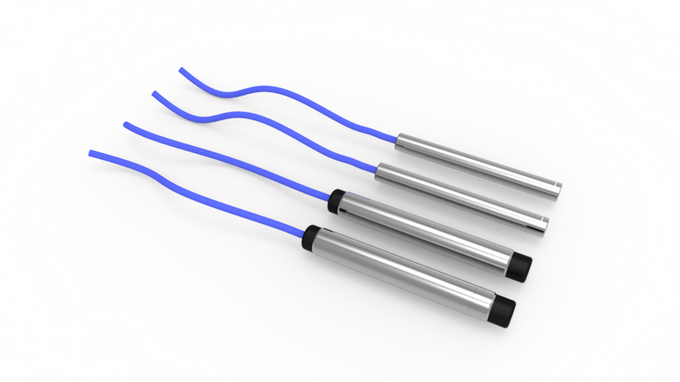
Drive-in piezometers, also called push-in piezometers, are designed for installation in soft clays, organic or fine grained cohesionless soils.
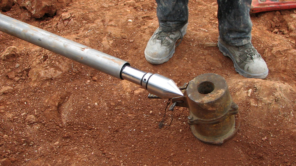
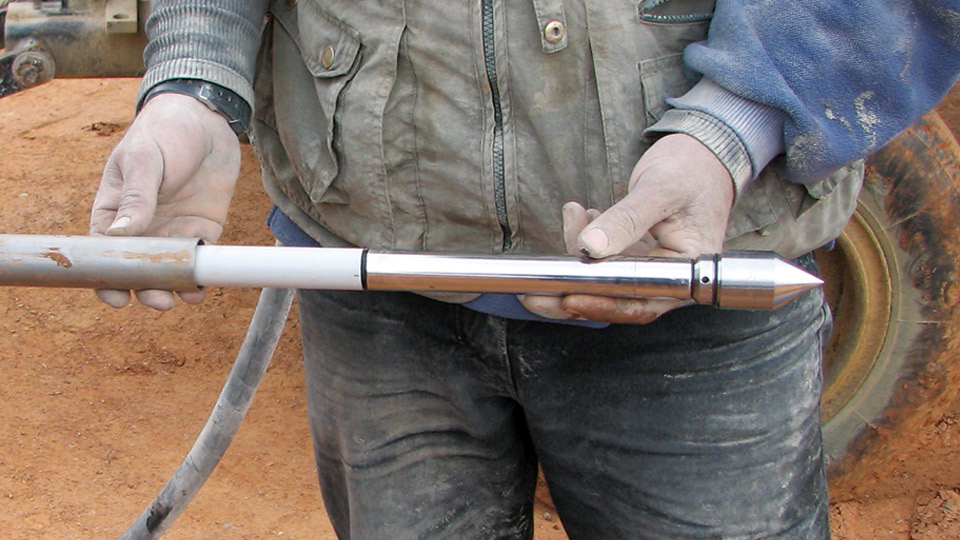
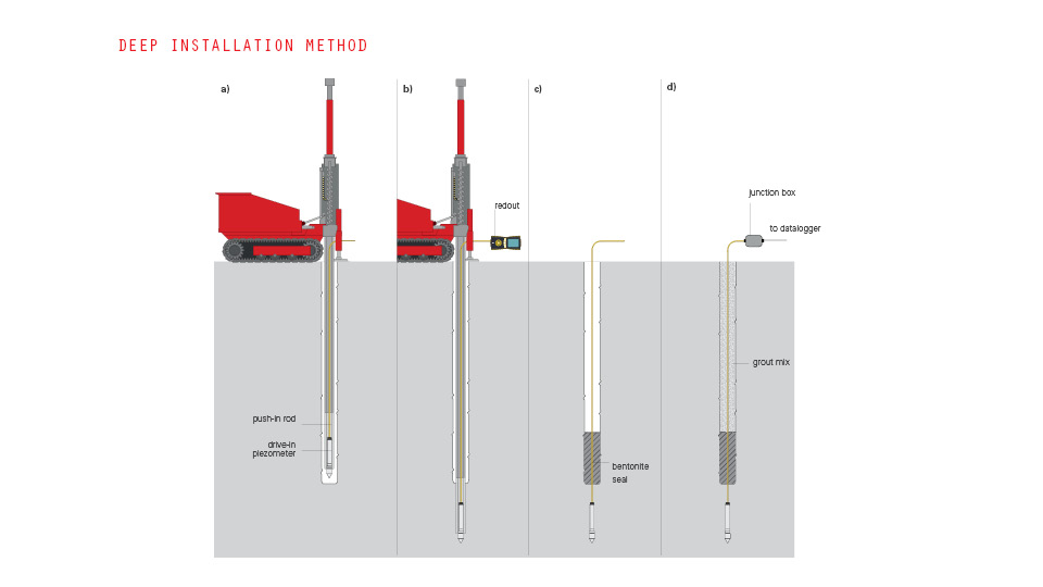
The piezometers are pushed directly into the soil using conventional cone penetrometer or drilling rods with adapters. The large diameter nose cone decreases the chance of overpressure while the piezometer is pushed into the soil.
APPLICATIONS
• Pore pressure in soft soils
• Dams and fill embankments
• Dewatering activities
• Natural or cut slope sites
• Deep excavations
• Diaphragm walls
FEATURES
• Cable length does not affect reading
• Long working life and reliability
• Built-in surge protection (vibrating wire only)
• Built-in temperature sensor
• Dynamic pore pressure monitoring (piezo-resistive only)
Resistive pressure transducer sensor is a spin off from thick film technology using the piezo-resistive characteristic of specific resistive inks. Resistors, formed using screen printing techniques, are deposited on a deformable ceramic diaphragm substrate to form strain gauge arrays. Strain changes from external loads applied to the deformable ceramic diaphragm result in resistance changes of the strain gauge arrays.
The electric signal from the strain gauge arrays is directly proportional to the stress applied to the diaphragm. Sensor is constructed of a ceramic, analogous to a crystal structure, to form a pressure diaphragm chemically inert with near perfect mechanical characteristics. Screen printed resistors are deposited onto the diaphragm to form a 4 arms Wheatstone bridge.
A fixed excitation voltage is applied to one diagonal of the circuit. Strains experienced by the diaphragm will change the values of the individual resistors within the Wheatstone bridge resulting in a bridge unbalance. This unbalance produce an output signal from the other diagonal of the Wheatstone bridge, directly proportional to the applied stress.
An electronic board converts this signal into 4-20 mA suitable for transmission over long distances to remote readouts or to data acquisition systems.
Vibrating wire transducer is essentially composed by a taut wire clamped at its ends and tensioned so that it is free to vibrate at its natural frequency. The frequency of vibration varies with the wire tension and thus small relative movements between the two end clamps.
With VW transducers frequencies rather than voltage levels are measured, so a dedicated readout/datalogger must be used to measure the resonant frequency. These ones excites the VW transducer, measures the response, performs some calculations on the response, and returns the result.
SISGEO VW transducer uses ‘pluck and read’ method and not ‘auto resonant’ method; when the readout/datalogger plucks the wire a magnetic attraction is created to the coil and the wire start to vibrate and it causes an alternating voltage of the same frequency of the natural frequency of the wire; the voltage signal is transmitted on the cable and read from the readout/datalogger.
VW transducers have a reputation for long expected life and long-term stability.
Readable by
Datasheet
Manual
Faq
Datasheet
Manual
Faq
Via F.Serpero 4/F1
20060 Masate (MI) – Italy
Tel. +39-02.95.76.41.30
info@sisgeo.com
| Cookie | Duration | Description |
|---|---|---|
| cookielawinfo-checkbox-analytics | 11 months | This cookie is set by GDPR Cookie Consent plugin. The cookie is used to store the user consent for the cookies in the category "Analytics". |
| cookielawinfo-checkbox-functional | 11 months | The cookie is set by GDPR cookie consent to record the user consent for the cookies in the category "Functional". |
| cookielawinfo-checkbox-necessary | 11 months | This cookie is set by GDPR Cookie Consent plugin. The cookies is used to store the user consent for the cookies in the category "Necessary". |
| cookielawinfo-checkbox-others | 11 months | This cookie is set by GDPR Cookie Consent plugin. The cookie is used to store the user consent for the cookies in the category "Other. |
| cookielawinfo-checkbox-performance | 11 months | This cookie is set by GDPR Cookie Consent plugin. The cookie is used to store the user consent for the cookies in the category "Performance". |
| viewed_cookie_policy | 11 months | The cookie is set by the GDPR Cookie Consent plugin and is used to store whether or not user has consented to the use of cookies. It does not store any personal data. |
| Cookie | Duration | Description |
|---|---|---|
| _ga | persistent | These third party cookies are saved to your device to allow us to use the Google Analytic service. They collect anonymous information on how visitors use our site. We use these to create website usage reports including the number of visitors, which websites they have come from to get to our site and the pages that were visited. |
| _gat | persistent | These third party cookies are saved to your device to allow us to use the Google Analytic service. They collect anonymous information on how visitors use our site. We use these to create website usage reports including the number of visitors, which websites they have come from to get to our site and the pages that were visited. |
| APISID | persistent | This cookie includes a mixture of pieces of information to measure the number and behaviour of users. |
| HSID | persistent | This cookie includes a mixture of pieces of information to measure the number and behaviour of users. |
| NID | persistent | This cookie includes a mixture of pieces of information to measure the number and behaviour of users. |
| PREF | persistent | This cookie includes a mixture of pieces of information to measure the number and behaviour of users. |
| SAPISID | persistent | This cookie includes a mixture of pieces of information to measure the number and behaviour of users. |
| SID | persistent | This cookie includes a mixture of pieces of information to measure the number and behaviour of users. |
| Cookie | Duration | Description |
|---|---|---|
| VISITOR_INFO1_LIVE | 180 days | youtube.com |
| VISITOR_INFO1_LIVE__default | 180 days | youtube.com |
| VISITOR_INFO1_LIVE__k | 180 days | youtube.com |